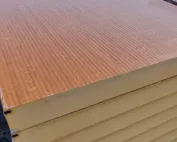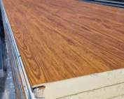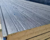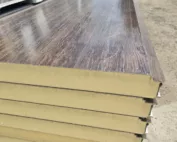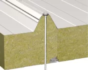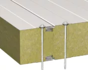
How should the structure be prepared for insulated wall panels with a mineral wool core?
Insulated wall panels with a mineral wool core
The structure for insulated wall panels with a mineral wool core should provide proper support, transfer of loads and a level mounting surface. It is not enough to set a few purlins at approximate spacings. The weight of the panels with a mineral wool core, wind, vertical or horizontal layout and openings must be taken into account. Checking the structure before material delivery helps avoid misaligned joints, makeshift packers and unnecessary cutting. A self-supporting panel transfers the anticipated loads between supports. This does not mean it replaces the main hall structure. Columns, purlins, bracing and connections form a separate system. Their stiffness and displacements affect the performance of the cladding. The panel should not be used to straighten or stabilise a poorly prepared frame.
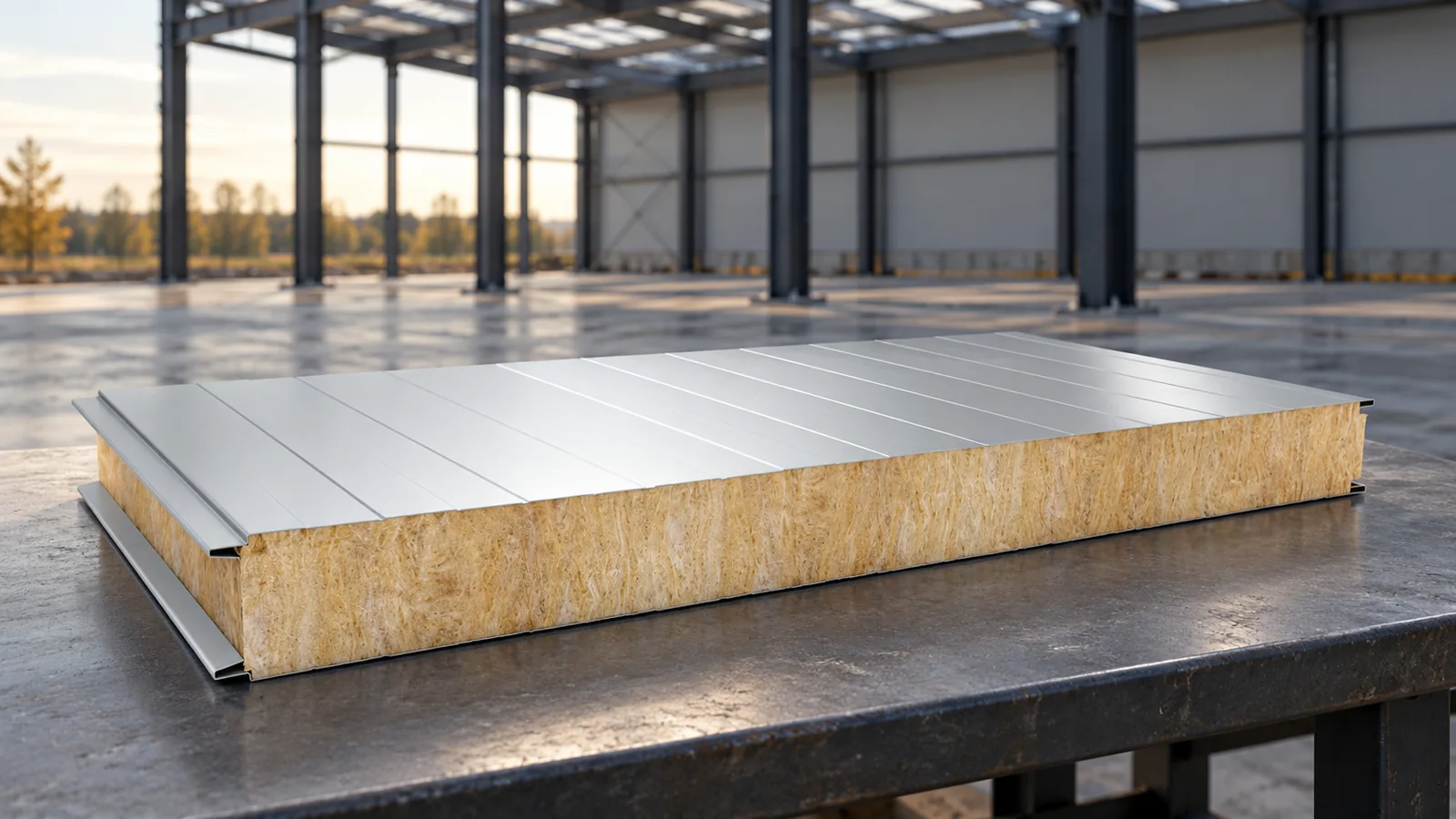
Can the panel replace the building frame?
A self-supporting panel transfers the design loads between supports. This does not mean it replaces the main hall structure. Columns, purlins, bracing and connections form a separate system. Their stiffness and displacements affect the behaviour of the cladding. The panel should not be used to straighten or stabilise an incorrectly prepared frame.
Before installation begins, the structural design and the panel layout must be known. This also applies to a small warehouse or an extension. It is important whether the cladding is to perform an additional role, for example in a fire solution. Such a task requires explicit confirmation. Simply describing an element as rigid does not provide a basis for assigning it any load-bearing function.
How should the direction and spacing of supports be selected?
Panels installed vertically are usually supported on horizontal substructure members. With a horizontal layout, suitably arranged vertical supports are required. The detailed arrangement results from the specific system and the façade geometry. At gates and windows, framing elements are added. The gap for an opening cannot be treated like an ordinary wall field.
The spacing is determined from calculations and the tables for the specific panel. Wind pressure and suction, facing thickness, colour and the single- or multi-span scheme are checked. Both load-bearing capacity and deflection are verified. Restrictions from the fire classification may be more demanding than the result of the wind calculation. The condition that applies to the intended use must be maintained.
What should be checked in the geometry of the structure?
Check the verticality of the columns, the level of the purlins and the relative position of their surfaces. The installation plane should correspond to the tolerances adopted in the documentation. Differences in the setting of the supports can cause stresses and visible waviness of the facings. Tightening the panel with screws to a crooked frame is not the proper way to correct these deviations.
Also measure the actual openings. The conformity of the gate dimensions with the drawing must be confirmed before ordering cut lengths and flashings. Check the space for seals and access for tools. Sometimes the structure looks correct, but the fastening falls too close to the profile edge. Such locations are easier to assess when the surface is not yet covered with panels.

Why do the width and thickness of the support matter?
Load tables are sometimes prepared for a minimum bearing width. A member that is too narrow changes the behaviour of the panel. It is therefore not enough to check only the distance between purlins. Suitable space for fasteners and proper surface contact are also needed. The bearing should comply with the detail for an end or intermediate support.
Steel thickness matters when selecting screws. Their tips have a specific drilling capacity range. A different solution applies to a different substrate material. It cannot be assumed that a screw for thin-walled profiles will be suitable for any steel element. The fixing schedule should be drawn up once the actual supports have been determined, not before they are selected.
How should junctions, bases and openings be prepared?
At the junction between the panel and the structure, separating or sealing tapes may be required. Their type and position follow from the system. They are not a random material for levelling out large irregularities. At the plinth, support, edge protection and water drainage must be provided. The lower part of the wall should not remain permanently wet from the substrate.
The opening framing should transfer loads in accordance with the design. A heavy gate or device should not be suspended from the thin cladding alone. Continuity of sealing and insulation at the reveals must be provided for. In a wall of a specified EI class, the details must comply with the required solution. Every new opening made after installation requires these relationships to be rechecked.
How should the substructure be inspected before installing the panels?
Prepare a record covering dimensions, spacing, support widths and their condition. Check the anti-corrosion protection and remove sharp elements that could damage the cladding. Confirm the storage location and the method of lifting the panels. The weight of long elements with mineral wool matters for work organisation and should not be assessed only at the moment of unloading.
Record and clarify any deviations from the design before covering up. An additional profile or a change in spacing may require an adjustment to the panel layout. Repair at this stage is usually simpler than dismantling a finished façade. A well-prepared structure allows focus on precise joining of elements. It is the basis of an even, airtight and durable wall.
7 branches. Materials closer to your project.