What determines the support spacing for insulated wall panels?
Sandwich panels
The support spacing for an insulated wall panel follows from the loads and the parameters of the specific product. The core, the thickness of both facings, the support arrangement, the colour and the permissible deflection all matter. The fixings and fire requirements must also be checked. There is no single safe distance suitable for all 100 mm panels. Reading a table only makes sense when its assumptions match the actual project. The wall works under wind pressure and suction. The values depend on the building, its location and the façade zone. Corners and edges may require different verification than the central field. Self-weight and the effect of temperature are additional factors. Loads should not be chosen on the feeling that the structure stands in a calm area.
What loads must be taken into account?
The wall is subject to wind pressure and suction. The values depend on the building, its location and the elevation zone. Corners and edges may require different verification than the central field. Self-weight and temperature effects are also involved. The loads should not be selected on the basis that the structure is felt to stand in a calm area.
The designer determines the values and how they are used. It is important to distinguish between characteristic and design loads in accordance with the table instructions. Some tables already include self-weight. Adding it again or omitting it in another case leads to an incorrect result. Before reading the span, check the units and the assumptions of the entire table.
Why is panel thickness not enough?
Two panels of identical thickness may have a different core, facings and joint. Changing the facing from 0.5 to 0.4 mm is not merely a change in mass. It affects the behaviour of the composite element. The table should relate to exactly the variant being ordered. Data from a stronger version must not be adopted simply because the difference is not visible in a photograph.
The single-, two- or multi-span arrangement is also significant. A panel supported on three supports does not behave in the same way as two independent shorter elements. The more favourable column should not be selected without matching the structural scheme. Check the span lengths and the conditions at the end supports. With openings or an unusual arrangement, the standard table may not be sufficient for an independent decision.
How do load-bearing capacity and deflection differ?
The load-bearing check concerns the ability to transfer the assumed actions. The serviceability check includes, among other things, the permissible deformation. A panel may satisfy one criterion but not the other. Therefore, one should not stop at the first favourable value in the table. The limitation resulting from the required checks must be adopted.
The L/200 condition means the ratio of permissible deflection to span length. For 3 m this gives 15 mm. This is solely an explanation of the notation, not a recommendation of 3 m spacing for any panel. A different criterion may apply in the design. The table instructions indicate how to compare ULS and SLS results. These designations cannot be treated as interchangeable ways of reading the same number.

What influence do colour and fire requirements have?
Dark facings heat up more strongly in the sun. The temperature difference between the two sides of the panel causes additional actions. Manufacturers therefore divide colours into groups and may limit lengths or support arrangements. Changing a light façade to a dark one may require the selection to be checked anew. This is not merely a cosmetic change to the order.
Fire resistance of the wall may be a separate constraint. The EI classification is sometimes relevant for a specific span, laying direction and joint detail. Even if the wind load table permits a larger support spacing, this does not mean the required fire class is maintained. The correct spacing must satisfy all conditions envisaged for the given application.
What should be checked on the supports themselves?
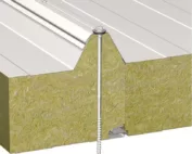
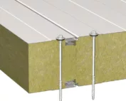
The bearing width, material and profile thickness are important. Tables may specify different minima for edge and intermediate supports. The correct number of fasteners and their load-bearing capacity must also be ensured. A panel resting on a member that is too narrow does not have the same conditions as in the catalogue calculations.
The geometry of the structure also requires checking. Purlins that are not set straight may force deformation of the panel during tightening. Large irregularities must not be corrected with random shims. Openings, corners and panel ends require solutions envisaged in the design. The selection of spacing is only complete once it is known how the element will actually be supported and fixed, and not after reading a single number from a table.
How should the data for checking the support spacing be prepared?
Collect the panel data sheet, sheet thicknesses, colour and planned installation direction. Include the building dimensions, the arrangement of supports and openings. State the loads assumed in the design and the fire requirements. For an existing structure, measure the actual spacings and widths. The documentation of an old hall does not always correspond to what is on site.
Ask for confirmation of the solution for the specific specification. If you change the panel or the type of support, the verification must be updated. It is not worth saving on a single purlin at the expense of uncertain behaviour of the entire wall. The correct spacing is the result of consistency between loads, panel and fixings. Only such an approach allows different cladding variants to be compared economically.
7 branches. Materials closer to your project.