Continuous Z-purlins: what to specify beyond the cross-section
Profiles and steel structures
The purlin layout is not just a series of independent steel sections. In suitable solutions, the Z-sections are connected over the supports to achieve continuous action. Such a connection changes the distribution of forces and the requirements for the joints. The profile, the lap and the supports must therefore be considered together. Choosing the height and thickness of the Z-section alone does not yet describe the roof structure. A single-span beam and a continuous system behave differently under load. In a continuous system, the zones over the supports and the interaction between spans matter. Results from one model must not be transferred to another. Each requires its own assumptions regarding connections and stiffness.
In this article
The scheme determines how it works
The design must correspond to what will be built on site. If continuity is provided by the overlap, its geometry and fasteners are part of the model. It is not enough to bring two profile ends into contact above the frame. The detail should genuinely provide the properties assumed in the calculations.
Different flanges help to build the lap
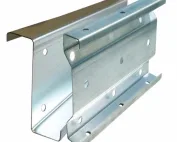
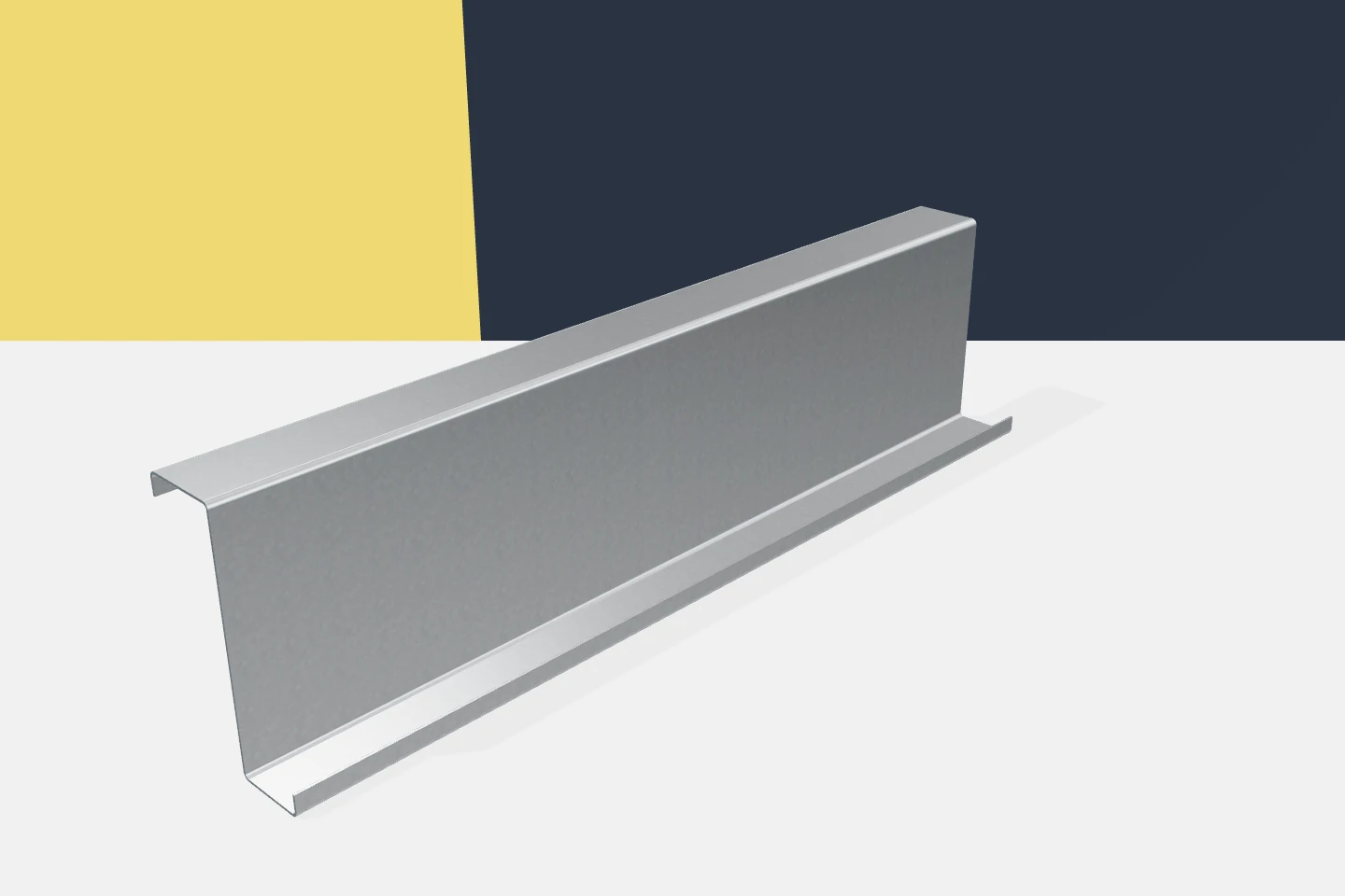
In many Z series, one flange is wider. This allows appropriately selected sections to be nested. The difference in width is therefore a functional feature. The correct installation direction and the compatibility of the interacting sections must be maintained. A random profile of the same height may not fit.
The dimensions of the lips and the bend radii also affect the fit. The corners cannot be treated as perfectly sharp lines. A well-prepared drawing shows the actual geometry. If the supplier changes, the feasibility of the node must be checked, not just the similarity of catalogue designations.
The lap length is not a universal rule
The extent of overlap between sections results from the specific solution. It depends on the adopted arrangement and the requirements in the support zone. Proportions should not be copied from a random example. Likewise, the number and position of screws must comply with the design.
If the frame spacing changes, it may be necessary to redefine the part lengths. The material schedule should be updated immediately. Leaving the old hole pattern with the new lengths leads to a discrepancy that is difficult to rectify at height. A single change in geometry should be visible in all related drawings.
Loads do not end with the weight of the roof
Purlins carry, among other things, the actions from the envelope, snow and wind. In certain cases, other foreseen loads are added. Wind suction requires separate attention because it changes the direction in which the system works. The assessment must not be limited to downward force.
The arrangement of loads across successive spans is important. The designer should analyse the relevant cases and combinations. Values from the tables may be used only where their assumptions are met. Similarity of span alone does not confirm that the whole model is consistent.

Stabilisation must have a genuine source
Sheets or sheet metal may contribute to restraining purlin displacement, provided this has been demonstrated. The properties of the cladding and its connection to the profile count. Not every sandwich panel provides the same conditions. The assumption of full support therefore requires agreement between the designs.
Before the cladding is installed, the situation is different. Bracing, restraints or a specific fixing sequence may be required. Cold-formed profiles should not be left in an arbitrary assembly state. The locations where materials may be temporarily stored on the structure must also be established.
When compiling the data, it is worth placing the purlin plan, the roof slope section and the support detail side by side. From these three drawings the length of the element, its direction and the actual level of bearing can be checked. Such a review helps to catch a discrepancy that the roof plan view alone does not show.
The node with the frame requires coordination
The support element must match the geometry of the frame and the purlin openings. Access to the bolts, the level of the flange and any offsets must be checked. The documentation should make clear who supplies the individual parts. The absence of a small support can halt the installation of an entire roof section.
The Z detail should not be replaced with a solution for a channel or sigma without checking. Sigma profiles may use different splice plates and methods of connection. Omegas belonging to secondary framing serve a further purpose. A common zinc coating does not make these elements structurally interchangeable.
The execution set should be complete
Full sections, material, lengths and hole patterns must be passed to production. Galvanised profiles should be marked according to their installation locations. It is worth linking the packing plan with the sequence of works. This makes it easier to keep orientation and to separate similar parts.
Before the roof is covered, the completeness of laps, connections and bracing is checked. The geometry of the panel bearing surface must also be confirmed. Only such acceptance shows that the execution matches the adopted scheme. The advantage of the continuous system results from the correct interaction of the parts, not from the use of zeds alone.
In the as-built documentation it is worth retaining the approved changes. For later installation of equipment this will allow the actual arrangement to be reconstructed. This is particularly important where lap lengths and sections vary between roof zones. A photograph alone does not always reveal these differences.
7 branches. Materials closer to your project.