From a building model to steel section production: completing the technical documentation
Profiles and steel structures
The structural model shows the position of elements, but it does not always contain everything the production plant needs. Full hole patterns, part orientation or a coating description may be missing. A material schedule, in turn, does not automatically clarify node details. Passing cold-formed profiles to production therefore requires organising several types of information. The aim is one consistent description of the finished element. It must be clear who selects the cross-section, who develops the connections and who produces the workshop documentation. Roles may be divided among several parties. They should not, however, leave an undescribed space between the general design and the finished part. Each scope requires clear confirmation.
In this article
Define the scope of responsibility
It is also worth establishing how changes are approved. A proposal from the works regarding feasibility does not always mean structural acceptance. On the other hand, the designer needs information about production constraints. An orderly decision flow helps resolve this collaboration before the series begins.
Link the model to an unambiguous cross-section
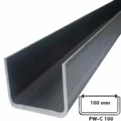
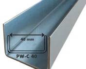
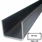
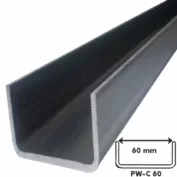
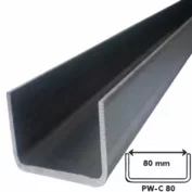
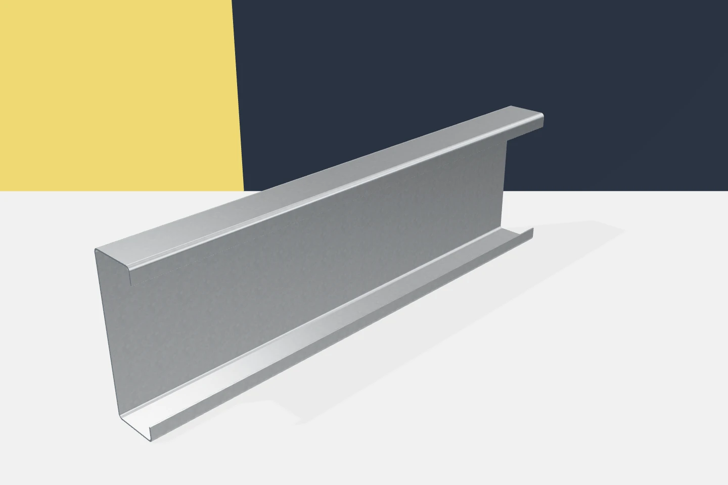
The designation C, Z or sigma alone is not precise enough. All relevant dimensions, thickness and material are needed. Omegas also require the full geometry, including flanges and web. The symbol should lead to a specific drawing or an agreed catalogue item.
If the model uses a simplified section, this must be indicated. It should not be accidentally treated as a production drawing. It is also important to distinguish between external dimensions and other reference bases adopted. Such a difference can determine the fit of the cover or the lap joint.
Every part needs an identifier
The part number should appear on the plan, the drawing and the schedule. It must allow parts with different lengths or hole patterns to be distinguished. Visually similar profiles should not receive a common designation if they are not interchangeable. This applies especially to left and right versions.
It is worth agreeing how finished parts are marked. A package label is often insufficient once the package is split. Identification should survive the journey from delivery to installation. This is not about extensive administration, but about being able to find the right part without measuring the entire stock again.
Hole patterns must have a common basis
The drawing must show from which end the positions are measured and from which side the profile is viewed. The diameters, shapes and orientation of the holes are important. Their conformity with the nodes of the main structure must be checked. A hole that is correct on one part may not fit another if they are described according to different bases.
Dimensions should not be carried over from an unverified sketch simply because they match the visual model. The required distances and the effect of the openings on the behaviour of the element need to be checked. Factory precision does not correct a faulty design. It replicates it across every manufactured part.

The material specification should be complete
Steel grade, thickness and coating are separate pieces of information. Galvanised profiles may have different protective requirements. They should not be replaced by a general note about a silver surface. The documentation must state which properties should be confirmed on delivery.
The required documents and the way they are linked to the product also need to be agreed. If part of the delivery uses a different material, the markings should make it identifiable. This is important for large orders split into stages. A lack of identification complicates both acceptance and later changes.
Close the interfaces with the envelope and services
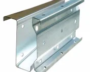
Before production, it is worth reviewing the panel support points, doors, skylights and service routing. C-sections, Z-sections and sigma profiles are often located precisely at the interface of these scopes. Omegas may be responsible for the next layer of the framing. Every dimensional change should also be assessed on the side of adjacent elements.
The check should cover access for assembly and the sequence of work. A node that can be drawn cannot always be conveniently bolted once the cladding is in place. Such situations should be clarified before ordering. This allows the division or detail to be changed without disturbing parts already produced.
The approved set must have a version
A defined set of documents with a date and revision marking should go into production. It must be established what applies in the event of discrepancies between the model and the drawing. After a change, replacing a single file is not enough. The impact on the schedule and on parts already made must be confirmed.
At acceptance, an unambiguous basis can then be referenced. Cold-formed profiles offer a major benefit from prefabrication when the information about them is well organised. Complete documentation shortens the path from design to assembly. It also reduces the need for ad-hoc decisions when fitting the steel.
A good way to close the stage is to check a few characteristic nodes. It is worth selecting an edge support, a connection between sections and a location at an opening. This does not replace a full design check, but it helps detect an inconsistency between the schedule and the details before repetitive production starts.
7 branches. Materials closer to your project.