Why the point of load application matters for a channel section in a wall rail or frame
Steel profiles and structures
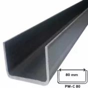
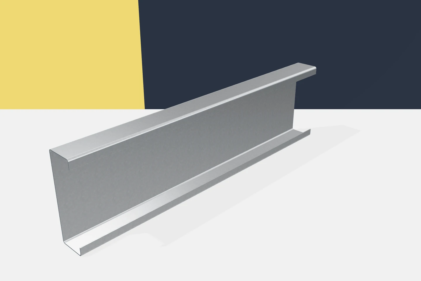
Channels are convenient in many construction details. They have an open cross-section, clear fastening surfaces and can be supplied as prefabricated elements. However, their selection should not end with checking the height and weight. The position of the load relative to the cross-section matters. In open cold-formed profiles, the way the force is introduced can affect torsion and stabilisation requirements. A channel arranged as a wall purlin does not necessarily behave the same as a similar element in a frame. The supports, force directions and connections change. The length of the segment without additional restraint of movement is also important. The selection result always refers to a specific structural scheme.
In this article
The same cross-section can behave in different ways
A single universal load-bearing capacity should not be attributed to the profile. Tables and calculations have a defined scope of application. If the orientation or the point of load application changes, conformity with the assumptions must be checked. The same material symbol does not settle these matters.
The opening of the channel must be oriented deliberately
The flanges are located on one side of the web. Inverting the profile changes the arrangement of surfaces available for fixing. It may also affect the load position and the feasibility of the connection. The drawing should clearly indicate the orientation instead of leaving it to the crew.
In practice, it is worth checking spanner access and the position of the cladding. Some solutions look correct in section but are difficult to assemble in the vicinity of a column. Such clashes are best resolved before production. However, installation convenience should remain consistent with the mechanical requirements.
The fastening position of the cladding is not irrelevant
Forces from the slab reach the profile through specific fasteners. Their line of action may be offset from the relevant cross-section axes. The resulting effects must be included in the model. Simple bending must not be assumed solely because the profile is horizontal.
Additional brackets require similar attention. A bracket mounted on the side may introduce a different force system than a load distributed over the cladding. Installations and equipment must therefore be coordinated with the design. The ease of drilling the flange does not justify loading the channel arbitrarily.
Support and stability are just as important as the steel
A higher yield strength of the material does not remove all limitations. Thin walls and an open cross-section may require appropriate stabilisation conditions. Possible buckling modes must be checked. Permissible displacements for the enclosure are also relevant.
Galvanised profiles with identical geometry may differ in material, but the coating alone does not determine load-bearing capacity. The specification should therefore separate steel, thickness and protection. Each of these parameters answers a different design question. Only their complete set describes the product needed for construction.

Openings and support zones require attention
Local forces are introduced into the profile near connections. Holes and cut-outs change its geometry. Their position should follow from the connection design. They should not be selected solely according to the available space on the web or flange.
If adjustment is needed for installation, its effect must be assessed before it is carried out. Enlarging a hole may change the working conditions of the connection. Cutting the lip affects part of the cross-section. These are technical changes, even if they take only a few minutes on site.
Connecting channels does not automatically create a new beam
Combining two profiles may be part of a designed solution. However, it does not mean that simply screwing them together at a few points ensures any assumed interaction. Proper connections and a model are needed. The transfer of forces between the elements and their common support must be defined.
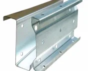
Similarly, a channel cannot be replaced by a zed or sigma profile on the basis of weight alone. Each cross-section has a different arrangement of walls and connection details. Omegas in grids have yet another role. The assessment of a substitute should cover the entire node, not just one catalogue parameter.
For example, it should be indicated whether the bracket is fixed to the web or to the flange. To the installer this may look like a minor difference, but it changes the point of force introduction. It is worth showing this on an enlarged detail together with the fasteners. This means the installation direction does not require interpretation on site.
Documentation should link calculations with installation
The drawings should indicate orientation, holes, fasteners and required supports. The schedule should allow each part to be identified. It is also worth defining the state in which the cladding and additional equipment can be installed. This reduces discrepancies between the model and the construction site.
Cold-formed channels are useful because their geometry can be adapted and they can be prefabricated. Their potential is best exploited when the installation details follow from a considered scheme. Cold-formed profiles then cease to be a collection of similar sections. Each element has a clearly defined function and method of load transfer.
At acceptance, it is worth comparing precisely those features that govern the model. These are orientation, fixing locations and the complete set of stabilisation. Measuring length and height alone will not reveal all significant discrepancies. The documentation should indicate what must be checked before the connections are concealed.
7 branches. Materials closer to your project.