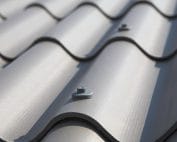
Finding thermal bridges in buildings with corrugated fibre cement roofs
Fibre cement sheets
Even a thick layer of insulation may not provide uniform protection if heat finds an easier path through the junctions. Thermal bridges often occur in places that are not visible once the work is finished. Fibre cement sheets are the outer part of the roof and do not automatically resolve these details. Asbestos-free fibre cement must be considered together with the structure and the insulation. It is precisely at their interface that the causes of cold strips or local dampness should be sought. A cold spot may result from easier heat flow through the material, but also from air leakage. The symptoms may be similar, but the repairs are different. A structural thermal bridge will not disappear by simply taping the membrane.
In this article
First distinguish conduction from draught
Adding insulation, in turn, will not always stop a draught through an unsealed joint. That is why the assessment starts with the cross-section and a visual inspection, not with the choice of repair product. Conditions in which the problem intensifies are helpful. A link with wind may indicate air flow. A consistent cold band along a structural element requires checking the continuity of the thermal protection.
Structural elements penetrate the insulation layer
A rafter or steel profile occupies part of the cross-section in which there is no insulation of the same kind as alongside. Materials have different thermal properties. Fibre cement sheets do not remove this variation on the outer side. The design should account for the contribution of the structure and the need for an additional layer to limit thermal bridges. Continuous metal elements leading from the interior towards the cold zone are particularly important. This does not mean that every steel structure is defective. It simply requires a correct detailing of the connections. Comparing insulation thicknesses between profiles alone ignores the influence of the material that separates those areas.
The junction between roof and wall is easily left unfinished
At the wall plate, the ring beam and the gable wall, different crews and stages of work meet. Each may complete its own section, leaving a gap at the junction. Fibre cement sheets on the roof slope will not reveal this gap from the outside. It should be checked whether the wall insulation connects with the roof insulation in the manner envisaged in the design. Maintaining ventilation is also important if it runs in the adjacent space. No free space should be filled without understanding its function. The detail must both limit heat loss and maintain the correct moisture behaviour of the building envelope. This requires a drawing of the connection.
Openings have a larger perimeter than the plan suggests
Windows, roof hatches and service penetrations cut through the protective layers. Each of their edges requires continuity of insulation and a sealed connection from the interior. Asbestos-free fibre cement does not replace these details, even when the external flashing is correct. Too tight a space for insulation or an incorrectly selected mounting element can create a local cold surface. A distinction should also be made between the flashing that protects against precipitation and the connection that limits heat loss. These are two tasks around the same opening. During an upgrade, it is worth checking them together so that, in repairing a leak, no hidden gap in the thermal protection is left behind.
Local moisture is often the result of a cold surface
If a section on the interior side is at a lower temperature, it may be more prone to condensation of moisture from the air. Not every damp patch therefore means a leak from outside. Fibre cement sheets may remain tight while the cause lies at the insulation junction. The assessment requires taking into account the temperature and humidity of the room. Excessive humidity may intensify the symptom, but reducing it does not always eliminate the constructional defect. On the other hand, improved insulation alone does not replace correct ventilation. It is worth separating the contribution of both factors so that the repair does not consist merely of painting over the mark.
The survey should answer a specific question
A thermal image can help identify temperature differences, but it requires suitable conditions and interpretation. Not every colour in the image proves a thermal bridge. Fibre cement sheets and the other materials have specific surface properties, and the result also depends on the weather. The survey is worth combining with documentation, visual inspection and internal measurements. It should be established whether we are looking for missing insulation, leaks or dampness. Sometimes several hypotheses need to be checked. Photographs taken during construction make it easier to locate the places where the layers meet. Without context, it is easy to plan a costly repair of the wrong section of roof.
Plan the upgrade with drying capability in mind
Adding insulation can change the temperature of the layers, the position of the gaps and the moisture conditions. The existing roof should not be closed up without checking its condition. Fibre cement sheets can remain if they are suitable for the new solution, but the decision concerns the whole building envelope. Leaks must be eliminated, the timber or steel assessed and continuity of the new connections planned. The method of reducing the thermal bridge should also be feasible at openings and walls. A thicker layer in the easily accessible middle of the field will not remedy the lack at the edge. A well-targeted improvement begins with the detail where heat actually bypasses the protection.
When modernising a roof with asbestos-free fibre cement sheets, first check the insulation connections. The choice of materials should be based on the identified path of heat loss and the full cross-section of the building envelope.
7 branches. Materials closer to your project.