Powerroof above-rafter insulation: coverage dimensions and design properties
PIR insulation
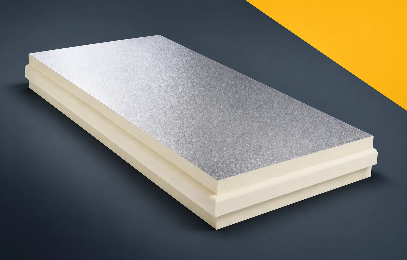
In the Powerroof description, a distinction must be made between the gross format and the coverage dimensions. The tongue and groove change the area actually covered by the board. The design should also specify the connection to the membrane, the fixing and the thickness required to achieve the intended thermal effect. Recticel Powerroof is a PIR board for above-rafter thermal insulation of pitched roofs. It has an aluminium facing and a tongue and groove on all four edges. In the application specification described as PIR boards, clearly indicate the above-rafter Powerroof layer laid over the timber structure of the pitched roof slope. Powerroof must be laid over the rafters while maintaining correct fixing of the entire covering, and the adopted variant must be clearly marked in the documentation.
In this article
Scope of data in the specification
A shortened record of the name alone is not sufficient, because continuous thermal insulation does not replace the elements that transfer forces from the covering to the structure. The functional assumptions are intended to allow the arrangement above the rafters to be used without omitting the support and changes in roof geometry. In the design documentation, include the course of the insulation layer, the height of the roof slope and the design of the connection to the timber elements, together with a reference to the relevant cross-section.
Lambda, thickness and thermal resistance
For thermal calculations of roof slopes, use the declared lambda of 0.022 W/(m·K) for Powerroof; the reduced thickness of the above-rafter layer follows from this value, not from the board format alone.
When comparing polyurethane boards in calculations, describe separately the resistance of the layer determined from the Powerroof thickness and the lambda of 0.022 W/(m·K). In the calculation of a roof slope with Powerroof, fasteners penetrating the thermal insulation layer must also be taken into account so that each value can be linked to the correct version of the calculation. The parameter must remain linked to the declared range, since a favourable value for the middle of the board does not automatically describe the result at every roof detail. Verification of the design should allow the space saving to be related to the result for the full cross-section rather than to the foam alone. In the calculations, retain the fixing parameters, the course of the junction at the eaves and the actual insulation thickness at the terminations so that a later change of material can be traced.
Product parameters versus assessment of the system
CS(10/Y)150 and D-s2,d0 are properties assigned to the Powerroof board; in a design they do not replace the assessment of the roof’s fire resistance and do not make PIR a non-combustible material.
In the table of mechanical and fire requirements, distinguish between the D-s2,d0 class and CS(10/Y)150 specified for the Powerroof board. The Powerroof Euroclass must be separated from the fire resistance and load-bearing capacity of the complete roof so that the product document does not replace the required assessment for the application. Evidence for one case cannot be extended arbitrarily, because neither the Euroclass nor the compression result on its own determines the load-bearing capacity of the covering fixing. The product and application documents should allow the mechanical and fire requirements to be checked at the correct level of assessment of the solution. When approving the material, compile the documentation for the entire roof and the way in which loads and wind forces are transferred to the structure with the actual configuration of the building envelope.
The Powerroof quantity take-off should be based on a coverage of 2380 × 1180 mm, not on the external dimension of 2400 × 1200 mm. It is worth showing this basis in the quantity calculation. Losses resulting from the geometry of the roof slope are added separately. The D-s2,d0 class declaration does not replace the requirement for the entire roof. The specification must retain both the properties of the board and the requirements for its application.
Moisture across the full cross-section
The aluminium facing of Powerroof does not seal penetrations: the solution must specify the water-draining layer and the method of forming laps and terminations around penetrating elements.
The analysis of moisture conditions should cover the point where the chimney passes through the thermal insulation and a separate water-draining layer. At the chimney, the rain-protection layer must be closed independently of the PIR board rebate, in accordance with the thermal and moisture conditions adopted for the building envelope. The description “polyurethane foam” does not complete the analysis, because the aluminium facing of Powerroof does not itself form the chimney flashing and its terminations. The adopted layers and their connections must allow the continuity of the water shield to be planned independently of the method of joining the PIR boards. In the specification, explain the course of the laps, the treatment of the penetration and the protection of the open roof slope during a break in installation, as well as the boundaries of responsibility of the individual layers.
Geometry and joint design
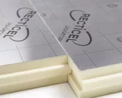
The gross format of Powerroof is 2400 × 1200 mm, while the coverage is 2380 × 1180 mm; the difference is made up by the tongue and groove. Transfer both dimensions to the working drawing so that the number of boards results from the area actually covered, not from the external outline.
In the construction drawing, describe precisely the difference between the 2400 × 1200 mm format and the 2380 × 1180 mm coverage. The number of Powerroof boards must be determined from the net coverage before adding cutting losses, and the method of verification must be shown on the construction drawing. This cannot be left solely to the installation decision, since ordering by the gross dimension understates the area that can actually be covered. The adopted geometry should make it possible to establish the number of full boards before adding losses at roof valleys and roof windows. The planned polyurethane insulation requires specifying how the coverage area, the number of rows and the layout of cut-offs around obstacles on the roof slope are to be verified during acceptance.
Conditions for purchasing and checking a substitute
In the Powerroof quotation, base the quantity on the net coverage, add losses from the roof geometry and the treatment of openings, and list separately the thickness of the new assembly at the eaves and at the windows.
When checking the “polyurethane insulation” item in the bill of quantities, analyse the scope of rebuilding the eaves and flashings after adding the Powerroof above-rafter layer. The cost of the above-rafter layer should account for changes to flashings resulting from the new roof slope height, and the agreed criteria must remain clear when assessing a substitute. Conformity of a single characteristic is not enough when the behaviour of the existing attic build-up may require a greater scope of external works. The material procedure should allow variants of the renovation to be compared, taking into account the interior space and changes in the roof geometry. Enter the net coverage, the bill of quantities for fixing, flashings and works at the existing roof windows in the conformity report, so that the decision is not based solely on the commercial description.
7 branches. Materials closer to your project.