Thermano Compact in construction details: dimensions, lambda and limitations
PIR insulation
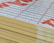
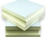
A detail should not leave the installer with nothing but the instruction “top up the PIR”. For Thermano Compact, the thickness, the edge and the connection to the surrounding construction must be specified. This ensures that the smaller board retains a specific function instead of becoming a random insert in a gap. Thermano Compact is a PIR board in the 600 × 1200 mm format, with a multi-layer facing containing aluminium. The smaller format is an important practical feature. In the application specification described as PIR boards, clearly indicate the small working area into which a 600 × 1200 mm board is easier to bring. The Thermano Compact format must be matched to the size of the working area and the available transport route, and the adopted variant must be clearly marked in the documentation.
In this article
Identification and intended use of the product
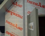
A shortened record of the name alone is not sufficient, because the convenient handling of a smaller board does not determine the correctness of the entire installation. The functional assumptions are intended to allow work to be organised on a small section without abandoning the design of the layers and joints. In the design documentation, include the dimensions of the installation location, the width of the access, and the planned position of each joint together with a reference to the relevant section.
Lambda, thickness and thermal resistance
The lambda value of Thermano Compact, 0.023 W/(m·K), is the starting point for determining the thickness: it is chosen so as to achieve the assumed thermal resistance in the location that will accommodate the given layer. The thickness and the resulting thermal resistance must be recorded against the specific detail, not only in a general schedule of materials.
When comparing polyurethane boards in calculations, describe separately the narrow strip of insulation whose thickness is limited by the existing building detail. The thermal resistance of the small insert should be assessed together with the geometry of the materials surrounding that fragment, so that each value can be linked to the correct version of the calculation. The parameter must remain linked to the declared range, since the influence of the narrow strip on the thermal bridge also depends on the geometry of the materials around it. Verification of the design should make it possible to assess the benefit of thermally insulating the detail without transferring the R result to the entire junction. Keep the width and thickness of the insert and the continuity of the thermal insulation in the adjacent fragments in the calculation, so that a later change of material can be traced.
Interpretation of mechanical and fire properties
The thickness of Thermano Compact determines the reading of the mechanical parameter. In the test at 10% deformation, boards up to 30 mm achieve the declared minimum of 150 kPa, whereas from 40 mm the minimum is 200 kPa. Enter the correct threshold against the variant designation in the specification. Record the reaction to fire E separately; the compression result is not a calculation of the load-bearing capacity of the finished detail.
In the table of mechanical and fire requirements, distinguish between the declared CS150 up to 30 mm and CS200 from 40 mm. The CS value for Thermano Compact must be assigned to the thickness shown in the board designation, so that the product document does not replace the required assessment of the application. Evidence for one case cannot be extended arbitrarily, because the appearance of two boards does not show which declaration range each of them belongs to. The product and application documents must make it possible to assess the pressure on the detail while retaining the data of the precisely selected variant. When approving the material, match the thickness on the label, the contact surface and the way the anticipated load is distributed with the actual configuration of the partition.
In the Thermano Compact specification, the 600 × 1200 mm format alone should not be left. The specific thickness and the BASIC or TOP variant are also needed. A change of thickness may mean moving to a different declared CS level. The choice of edge, in turn, affects how the board is cut and how offcuts are joined. All this information should be assigned to the place of application, not only to the general materials schedule.
Separation of the functions of the sealing layers
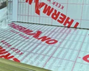
The Thermano Compact facing does not replace damp-proofing. The detail must therefore describe the flashings and the junctions with the window, wall or substrate and state how the sealing layers connect at the edges of the insert, not only at its centre.
The analysis of moisture conditions should cover the junction of the small PIR insert with the substrate and the flashing at the location exposed to water. The protection of the small section of insulation must also cover its junctions with the surrounding material in accordance with the thermal and moisture conditions adopted for the building envelope. The description “polyurethane foam” does not close the analysis, because the facing surface may be undamaged and water may still enter through an unsealed side. The adopted layers and their connections must allow the detail to be protected together with its terminations instead of protecting only the middle of the board. In the specification, explain the method of water drainage, the condition of the flashing and the connection of materials on all sides of the insert, as well as the limits of responsibility of the individual layers.
Support and details on the drawing
The BASIC or TOP variant must be stated in the detail description itself, because cutting a TOP board may remove the groove from one edge. The drawing should therefore show where the factory lap remains and where a new edge is created and how the joint will be made.
In the construction drawing, precisely describe the offcut cut from the TOP board which, after shortening, loses part of the factory tongue. After cutting the TOP board, the joint between the retained tongue and the new straight edge must be planned, and the method of verification must be shown on the construction drawing. This cannot be left solely to the installer’s decision, since using the offcut requires ensuring support and proper sealing of the new joint. The adopted geometry should allow the cutting plan to be matched to the actual direction in which successive pieces are laid. For the specified polyurethane insulation, state how the position of the tongue on each used element is to be checked, as well as the stability of the resulting strip at the perimeter during acceptance.
Conditions for purchasing and checking a substitute
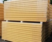
Determine the number of Thermano Compact boards from the cutting plan for the detail elements, not from the sum of the recess areas. A narrow offcut from one location may not be usable in the next, which changes the number of packs required.
When checking the “polyurethane insulation” item in the bill of quantities, analyse a set of several small pieces whose combined length does not show the number of full boards. All the necessary offcuts should be laid out on the 600 × 1200 mm format before purchasing packs, and the agreed criteria must remain clear during the assessment of an equivalent product. Agreement of a single characteristic is not enough, since narrow remnants may not fit the next location despite matching material thickness. The material procedure should make it possible to reduce waste by matching the cutting plan to the actual shapes of the required elements. Enter the cutting sketch, the number of full boards and the possibility of safely using the remaining pieces in the conformity report, so that the decision is not based solely on the commercial description.
7 branches. Materials closer to your project.