PIR floor insulation: specifying CS, creep and loads
PIR insulation
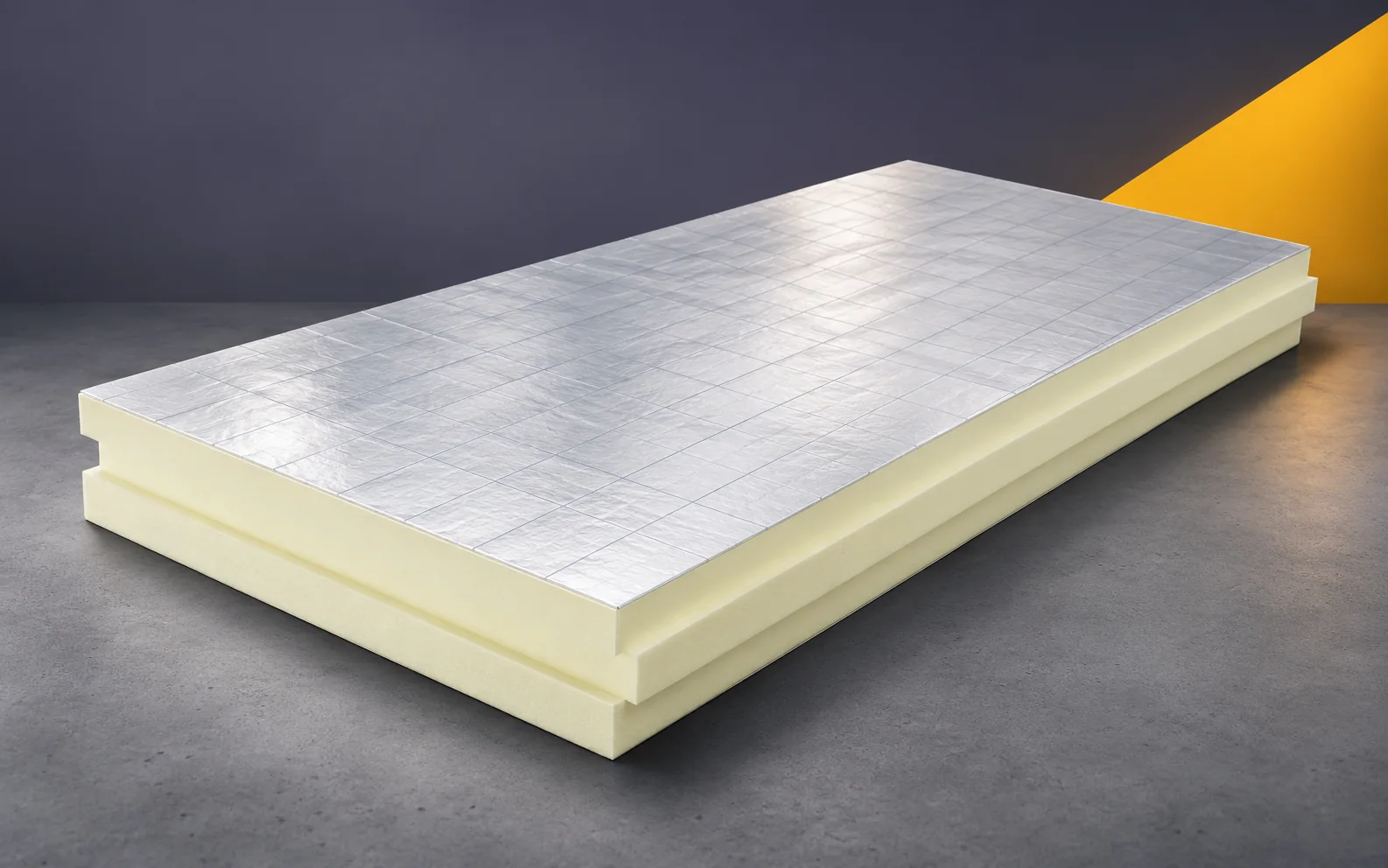
The floor specification must combine thermal performance with mechanical requirements. PIR boards can help where the available height is limited, but their selection should not end with CS(10). Information is needed on the intended use, the permanent compressive stresses and the load-distributing layer. Low thermal conductivity allows an effective insulation layer to fit under the screed. The cross-section should show all levels from the substrate to the finish. This makes it possible to check whether the proposed insulation thickness fits within the assumed height. The layer schedule should separate the thickness of the insulation from the thickness of the screed and the finish. It is also worth stating the permitted substrate preparation.
In this article
The space beneath the floor
This means the bidder cannot use the entire contingency solely for PIR. Comparing thinner variants makes sense while preserving the function of the other layers. The documentation should show the finished level to which doors, stairs and adjacent rooms refer.
What CS really means
In floor documentation, the CS(10) value must be assigned to a specific compression test condition, not to permanent service load-bearing capacity. Therefore, alongside the CS designation, data on creep and the design load must be stated, because each of these pieces of information relates to a different stage of the insulation’s performance. Only parameters separated in this way allow verification of whether the mechanical requirement corresponds to the manner and duration of load action in a given room.
These are pieces of information with a different meaning and must not be used interchangeably. CS(10) describes a specific test point, whereas creep refers to deformation increasing over time. These data are not interchangeable. If a product does not declare the required parameter, it must not be added on the basis of a material with a similar name. The correct data must be obtained or the selection changed. The specification should link the mechanical requirements to the actual function and the period of load action.
Support and load distribution
In the design and specification, the method of ensuring continuous support of the board must be indicated, because a bump or void beneath the insulation changes the transfer of forces. The description should link the load distribution to the substrate and to the support of the insulation, so that the path of pressure transfer from the distributing layer to the substrate can be traced in the drawings and in the specification.
The specification should describe the approved solution instead of shifting the entire assessment onto the PIR board’s data sheet. The load-distributing layer has its own stiffness and rules of execution. Its interaction with the insulation also depends on full support and the geometry of the load. It is worth identifying particular locations, such as upstands, supports and edges. None of these can be assessed by dividing the mass by the area of the whole room. The floor description should make it possible to verify the full load-transfer path.
Compatibility with underfloor heating
With underfloor heating, the insulation limits heat loss to the cooler substrate, but it does not determine the system output or the flow temperature. In the heating part of the design, the compatibility of the board with the floor heating system must therefore be confirmed separately, rather than deriving these parameters from the thermal function of the insulation alone.
At the same time, the requirements for the screed, movement joints and the routing of services must be specified. In a heated floor, the installation and material requirements must be coordinated. The documentation should specify how the pipes are fixed, the separating layers and the movement joints. The thermal properties of PIR help to limit the flow to the substrate, but they do not determine the entire output of the system. A change of finish may require the heating part to be reassessed. This relationship should be retained in the specification of substitute products.
Moisture and impact sound
In the design of a floor on the ground or in a wet room, it must first be established where the damp-proofing layer runs, and only then should the role of the PIR be assessed. The low water absorption of the board itself does not take over the function of the damp-proofing layer, so both tasks must be kept separate in the cross-section drawing. Acoustics are considered separately: the thermal conductivity parameter says nothing about impact sound, so the acoustic requirement needs its own data and details at the edges of the building element.
The thermal conductivity parameter is not a substitute criterion for impact sound. For acoustics, separate criteria are needed for the complete floor. A rigid thermal board should not be specified as a replacement for a resilient layer without data. The detail of separating the screed from the walls is also important. If a multilayer system is designed, each layer should have a defined function. This makes acceptance easier and prevents the removal of an element that looks superfluous but is needed.
Selecting the board according to the room’s function
The function of the room determines how the load is assessed: a residential room is considered differently from a technical room, and differently again from a storage area. In a warehouse, knowledge of the racking layout and the loads of their feet is necessary, because without this information the transfer of forces through the floor cannot be assessed. Only on this basis can insulation variants be compared and the scope of permitted use described in the specification.
The lack of this data must be resolved before accepting a material substitution. Before approving a warehouse floor, the geometry of the racking and the loads of their feet must be known. It is also worth taking into account the possibility of a later change of arrangement. The scope of permitted use should be communicated to the client. The selection of insulation can then be based on verifiable data. The lack of information about the equipment should not lead to the automatic adoption of the board with the highest CS in the available range.
Example of pressure and deformation
For orientation: a force of 2.25 kN over an area of 0.02 m² corresponds to an average stress of approximately 112.5 kPa, and over an area ten times larger it would be ten times smaller. This is merely an illustrative calculation that does not take into account the distribution of forces in the screed and does not determine the permissible load on the PIR. Similarly, 10% deformation of a 110 mm board would mean an 11 mm change in thickness, which illustrates the difference between the CS test point and the requirements placed on the finished floor. The documentation should therefore specify the particular polyurethane board product together with its mechanical data, bearing in mind that polyurethane insulation limits the thickness of the section but does not replace a load-distributing layer, and that the polyurethane foam in the core does not constitute a finished floor.
7 branches. Materials closer to your project.