PIR in flat roof design: material properties, drainage areas and layers
PIR insulation
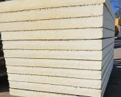
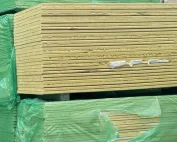
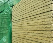
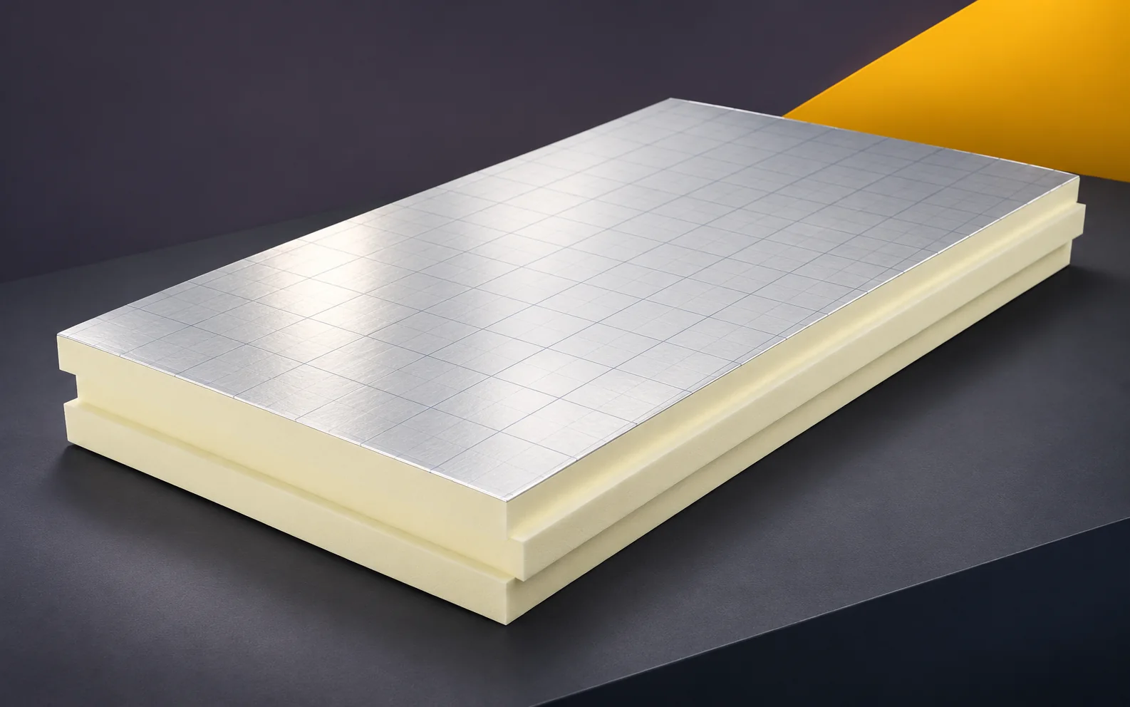
A flat roof with PIR requires a consistent thermal, mechanical and moisture specification. The design should combine the type of facing with the waterproofing, and the slope plan with the drains. This allows delivery and execution to be assessed against a single, clear set of assumptions. PIR boards for a flat roof are selected according to how the covering is to be executed. Aluminium laminate, glass fleece and bitumen-coated facing are not interchangeable surfaces. The type of facing must be stated alongside the required thickness and lambda. Otherwise, a substitute may meet the thermal parameter and yet not be suitable for bonding. It is the facing that interacts with the adhesive or the covering layer.
In this article
Facing matched to the waterproofing
Equivalence therefore cannot be limited to the lambda value. The properties required for the chosen method of fixing must also be specified. Such a description makes it possible to assess a proposed substitution before delivery, without creating a new assembly by chance on site.
Slopes directing water to the drain
In the drainage design for a flat roof, it is first necessary to establish the route by which water is to reach the outlet or the drainage edge, and then to assign that route a specific slope-bearing element: the structure, the substrate layer or PIR tapered boards. The slope drawing must state the minimum and maximum height of the entire assembly, because these two values determine both the insulation thickness and the position of the details at the drain.
For the thermal assessment, the actual variation in thickness is needed, not just its average. The slope plan should include designations of elements and heights at points relevant to drainage. The thermal calculation must be based on the actual variation of the cross-section. The arithmetic mean of the thickness does not always describe the thermal resistance of the entire surface that corresponds to it. It is worth separating the constant layer from the tapered layer. This facilitates both ordering and checking the minimum insulation at the drains.
Fixing and the effect of wind
Wind load is transferred from the covering through the successive layers and connections down to the substrate, which is why it is not enough in the design merely to state that the system is mechanically fixed, bonded or ballasted — each of these imposes different conditions. The selection of fixings must be considered together with the type of substrate and the designated wind action zones, not as a separate issue.
The diagram should be readable on site without anyone having to guess where the boundaries are. The fixing assumptions cover the type of substrate, its load-bearing capacity and the boundaries of the roof zones. If the old layers remain, their influence on the choice of method must be specified. The design should provide a basis for checking the number and position of the fasteners or the method of bonding. The contractor should not have to determine on their own where the edge zone begins. Material compatibility is needed throughout the entire load transfer path.
Loads above the insulation
Ballast, installations and service traffic are loads that are distributed differently across the roof surface than under an even layer of insulation — beneath a small support of a unit, a concentrated load arises. The design should therefore indicate the locations of planned units and the concentrated loads assigned to them, so that the choice of insulation corresponds to the actual distribution of forces.
Averaging the weight over the entire roof surface does not replace checking the contact between the support and the system. The mechanical requirements for the insulation should be linked to the load map. Units, ballast and service traffic do not always act uniformly over the entire roof surface. It is worth defining the contact areas and the required load-distributing layers. The CS data do not replace the assessment of long-term performance. The design should state on what basis the board was selected in particularly loaded locations.
Airtightness and moisture in the system
In a flat roof design, water vapour, PIR insulation and waterproofing are not considered separately — they form a system whose performance depends on the continuity of each layer. Therefore, the technical description should state how the continuity of the layer restricting vapour flow is maintained at seams, edges and installation penetrations, and not only what diffusion resistance the material itself has. The internal conditions are input data for the moisture analysis, so they should be recorded in the design as an assumption to which the assessment of the cross-section refers.
A roof over a damp zone requires an assessment that reflects actual service conditions. The interior parameters should follow from the function of the building, not from a convenient default value. A damp zone may require a separate analysis of the build-up. The vapour-limiting layer also needs continuous joints at the edges and at installations. The material’s diffusion resistance alone does not describe air leakage. In the documentation it is worth separating the requirements relating to both moisture transport mechanisms.
Access to details during renovation
The scope of a roof modernisation follows from the condition of the substrate and the concealed layers, which is why the design should provide for exploratory openings and measurements as the basis for determining what is to be replaced. The criteria for retaining old layers must be described in the specification so that the decision after opening up the assembly does not depend on the contractor’s discretion. Such a provision links the assessment of the existing build-up with the subsequent selection of PIR layers and allows consistency to be maintained between design and execution.
The contractor should know which result of the inspection or exploratory opening changes the scope of replacement. In a renovation, a method for making decisions after opening up the layers is needed. The design can specify the criteria for rejecting damp or non-load-bearing material and the scope of further assessment. This allows reaction to the actual condition without improvisation. New heights at the outlets and parapets must also be taken into account. Replacing the board with a thinner one should not be the only tool for resolving detail conflicts.
Example of the height of the slope layer
A height drawing helps to identify a conflict between the insulation and the parapet. In a simplified example, a section 11 m long and a slope of 2% mean an increase of 220 mm. If the start of the layer is 120 mm, at the other end we obtain 340 mm. The figures explain the geometry; they do not recommend a specific fall and do not replace the design. The arrangement of the drains, the actual taper plan and the system data are needed for selecting the layers and for the thermal calculation. The order should identify the facing of the PIR board and its compatibility with the covering; the mere designation of polyurethane insulation does not confirm this connection. The core does not take over the function of the waterproofing. The roof description must also cover the other layers and the method of fixing the whole.
7 branches. Materials closer to your project.