Omega sections for façades: matching the support frame to the cladding
Profiles and steel structures
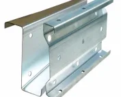
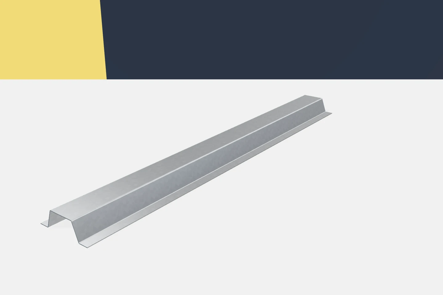
Façade design involves more than choosing a colour and surface layout. The cladding needs a suitable substructure, and the substructure needs connections to the structure. Omega profiles can form part of this system. Their hat-shaped cross-section provides specific fixing surfaces and layer offset. To make use of these features, geometry, loads and installation method must be coordinated. A profile catalogue alone does not resolve the entire façade detail. The architect describes the façade plane and cladding layout. The structural engineer defines the supports and how forces are transferred. The cladding supplier specifies the conditions for its fixing. All this information should come together in one coherent solution. Otherwise, each part may be correct on its own but not fit with the others.
In this article
A common reference point for several trades
It is worth establishing which surface the dimensions refer to. The construction line, the outer face of the substructure and the face of the finished cladding are not the same. An error here may become apparent at corners or flashings. Omegas should be dimensioned with reference to the actual layer arrangement.
Fixing surfaces must be sufficient
The flanges and the central part of the profile have defined widths. Depending on the solution, they serve different connections. The space for fasteners and the required edge distances must be checked. A slight increase in the height of the omega will not solve a lack of width in the fastening zone.
The substructure spacing should correspond to the cladding requirements. However, its permissible span is not the only criterion. Profiles, fasteners and the substrate must be checked separately. The entire system must carry the anticipated load, not merely support the weight during installation.
Layer offset changes the behaviour of connections
If the cladding is further from the structure, the geometry of load transfer changes. This may affect the requirements for brackets and fastenings. The offset should not be increased arbitrarily by adding shims. Such a solution requires assessment just as much as a change of profile.
The documentation must also specify any adjustment range. This makes it easier to account for actual substrate tolerances. However, adjustment should remain within the limits of the designed detail. It must not be an open licence for arbitrary positioning of the substructure.
Displacements and temperature require coordination
Facade elements are subject to temperature changes and structural movements. The fastening method should correspond to the requirements of the cladding system. Some details require specific movement capabilities, while others act as fixed points. Their role should not be changed on site without verification.
A slotted hole or separation of the substructure sections may be part of such a solution. However, it must follow from the documentation. Simply making a larger hole does not create a correct movement detail. The direction of movement, the fastener and the way it is seated also matter.

Moisture and ventilation are part of the wall assembly design
In systems requiring a ventilated space, its appropriate connections and permeability must be maintained. Omega alone does not guarantee such performance. The sequence of layers, flashings and water drainage points must be checked. The profile should not create an unforeseen obstacle or moisture pocket.
Galvanised profiles are selected for the exposure at a given location. The zone hidden behind the cladding does not always have to be dry. The fastener materials and direct contacts are also important. Surface protection should be consistent with the whole detail, not chosen independently of it.
Omegas do not replace other components just by name
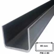
C-sections, Z-sections and sigma profiles have different geometries and typical tasks. They may coexist with omegas in the same façade or hall. However, each profile should have a defined function. The cladding frame does not automatically become a wall tie or structural bracing.
If a change of shape is considered, the connections, bearing surfaces and displacements must be checked. Similar mass or height is not enough. Sometimes a different section will facilitate execution, but it may require changes to the details. Such a decision is best made before ordering serial parts.
A practical check is to trace through the corner detail from the substrate to the façade face. All offsets should be counted and it should be seen whether the flashing has room for fixing. The same review is worth carrying out at the window opening. That is precisely where dimensions from several independently prepared drawings meet.
Acceptance of the substructure should precede installation of the cladding
The plane, spacing, orientation and completeness of the fixings must be checked. The condition of the surface and conformity of the execution with approved solutions should also be assessed. After the façade is closed, access to some locations will be more difficult. It is worth keeping documentation of this stage.
Cold-formed omega profiles help create an orderly substructure. Their usefulness stems from repeatable geometry and the ability to adjust length. However, full benefit comes from coordination of the entire envelope. Thanks to this, the frame meets both the needs of the cladding and the requirements of the structure.
When changes occur during execution, the shared drawings must be updated. A correction to layer thickness or panel layout may affect the spacing of the omegas. The information should reach the frame installer before the next batch is produced. This is a simple condition for maintaining the consistency of the entire façade.
7 branches. Materials closer to your project.