Flat roof drainage. Trace the water from each catchment to its discharge point
Flat roof – the path of water
A flat roof drains water only when all elements of the water path work together. This covers the division into drainage areas, falls, outlets, gutters and emergency drainage. A parapet changes the details but does not remove the need to set out falls or check flow. An outlet must sit at the actual lowest point of the drainage area, not at a point that is convenient on the drawing. An opening in the parapet without checking height and dimensions is not a complete solution. After the works, the entire water path must be inspected and the documentation retained. The scope covers flat roofs with and without a parapet, with external or internal discharge. It does not replace design calculations or the selection of system parameters.
In this article
Divide the roof into water-collecting areas
First establish which parts of the roof surface drain water to a specific outlet or edge. The division into catchment areas determines the number and arrangement of outlets, not the other way round. Only then can you check whether each point is genuinely the lowest point of its catchment area. A convenient layout on the plan is not enough on its own, because local steps and supports change the path the water takes.
The catchment area also includes the zones at the parapet and at the eaves, where water lingers longest. These are precisely where the risk of ponding and of leakage at the lowest detail becomes apparent. The division of areas should therefore take critical points into account, not just the surface area. Without this, the later selection of outlets and gutters rests on an assumption the roof does not meet.
Form the falls towards the correct outlets
The falls must be coordinated with the structure and the thickness of the layers. They can be formed in the substrate or in a screed layer, including PIR boards cut to a variable thickness. The parameters of such a variable-thickness build-up require calculation. The low lambda value of PIR helps maintain thermal performance within a limited height, but it does not replace the drainage geometry.
The outlet must sit at the actual lowest point, with no humps or leftover material around it. The outlet flange must match the type of waterproofing, and its connection requires precise workmanship. The overflow heights and the termination of the waterproofing follow from the design, not from the aesthetics of the flashings. Heating the outlet complements a correct design; it is not a repair for faulty geometry.
Compare drainage through a parapet and at the eaves
A roof with a free edge directs water into an external gutter. The gutter cross-section, the arrangement of downpipes and the connection to the roofing must be selected. A gutter set too high or waterproofing incorrectly terminated will hold water at the edge. It cannot be assumed that during heavy rain the water will simply fall clear of the roof. Eaves flashings and the termination of the insulation are also important.
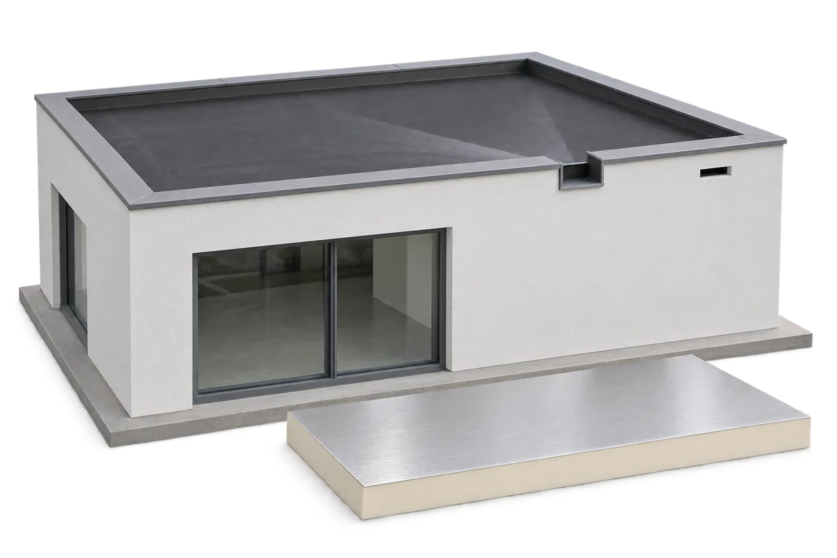
A parapet forms a perimeter upstand, so water can accumulate at a blocked outlet. Drainage is routed to roof outlets or through openings in the parapet. The opening alone, without checking its height and dimensions, is not a complete design. A penetration through the parapet requires a detail for the edge penetration and for discharging the water to the outside. A parapet changes the details but does not remove the need for falls and flow control.
Design the response to a blockage
The emergency route must have a defined capacity and a defined discharge path. It must also work when the main drainage is restricted by leaves or other debris. Emergency water should be directed where it will not cause unforeseen damage. It must not flood entrances, facades or sensitive areas. Regular operation of the overflow is not the normal way of handling ordinary rainfall.
Rainfall can exceed the value adopted for sizing the main outlet, so the behaviour of water during exceptional rainfall or in the event of a blockage must be defined. Outlet dimensions follow from the calculations. A gravity system carries water at partial pipe filling and with the required falls; with sufficient inflow, the pipes can fill and use the height difference. Debris is then removed and the condition of the seals assessed.
Leave access for cleaning and inspections
The finish layer must not obscure areas requiring cleaning. Gully baskets must be checked for compatibility with the outlet; they must not be replaced with a grating that restricts flow. Self-cleaning attributed to system components does not remove the need to inspect gullies. Green roofs and terraces require access via suitable inspection elements. A visible emergency discharge can indicate the need for a check.
Access also covers the route beneath the roof where the system runs inside the building. The choice between external and internal, gravity and vacuum systems affects the façade, the space beneath the roof and the ability to inspect the pipework. A vacuum system requires calculation of the entire network, not just selection of the outlets. It can reduce pipe diameters and the number of stacks and does not need a pump to generate the vacuum, but it does not remove the need to design for low-rainfall conditions.
Check the water path beyond the roof as well
After the works are completed, the entire water path must be inspected and documentation retained. This covers outlets, gutters, downpipes, penetrations through the parapet and discharge points. Pipes must not be shortened arbitrarily, diameters changed or outlets added without recalculating the system. The solution should account for thermal movement and winter conditions. Only a system verified in this way protects the roof from unplanned water accumulation.
The assessment covers the weight of retained water and the risk of leakage at the lowest detail. The average thickness of the insulation package does not describe local conditions at the outlet and parapet. Good drainage combines correct calculation, careful workmanship and regular servicing. The emergency route limits the effects of a blockage or rainfall exceeding the design value, but does not replace a properly functioning main network. This completes the responsibility for keeping water on the designed path.
7 branches. Materials closer to your project.