Documenting walls with PIR insulation: ETICS, diffusion and junctions
PIR insulation
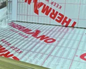
The description of the PIR board for the wall should indicate its position within the building element and the type of finish. ETICS places different requirements than a ventilated façade. The specification must also cover the continuity of seals, the details around openings and the drying conditions of the entire system. PIR boards can form a continuous layer of thermal insulation on the outer side of the wall. This position helps to limit thermal bridges associated with structural elements. The design should indicate the route of the insulation across the ring beam and the connection to the floor slab. This makes it possible to assess thermal bridges outside the regular field of the wall. The calculation of the wall should separate the regular field and the spatial connections. The ring beam, the floor slab and the reveal may require different data than a flat section of wall.
In this article
Continuity of the wall thermal insulation
Continuous PIR helps to limit some heat flow paths, but its route must be known. The drawings should show where the insulation begins and ends. This makes it easier to assess whether the proposed replacement preserves the adopted geometry.
PIR beneath render in the ETICS system
ETICS is a set of interacting layers. It comprises the insulation material, adhesive, fixings, reinforcing layer and finish. For ETICS, all intended components must be compatible.
An arbitrary PIR board should not be entered as a replacement for a product intended for use under render. In the ETICS specification, the compatibility of the insulation material with the other components must be maintained. The requirements also cover substrate preparation and the execution of the reinforcing layer. A general reference to a lightweight board with low lambda is not sufficient. The surface of the product must be suitable for this application. The description should make it possible to identify the compatible set in the tender, at delivery and during installation.
Ventilated façade and cavity wall
In a ventilated façade design, the roles of the cladding, the supporting substructure and the cavity must be kept separate: the finish is fixed to the framework, and the designed cavity remains behind it. In a cavity wall, the insulation interacts with the wall layers and the anchors, so its position follows from the arrangement of these elements. For a façade on a framework, the documentation must cover load transfer and the penetration of the thermal layer by load-bearing elements.
A description of the board thickness alone does not resolve this junction. The façade supporting substructure requires a separate structural assessment, but it also affects insulation performance. Its components may penetrate the layer or require cut-outs. It is worth coordinating the layout of the brackets with the board format. The intended function of the cavity and of water drainage must also be preserved. Documentation prepared in this way reduces the need to randomly adapt the insulation to a grid that has already been installed.
Water vapour and the ability to dry out
In the moisture analysis, two mechanisms must be distinguished: water vapour transmission through materials and the flow of moist air through leaks. The data for the calculations should come from the actual facing, not from an assumption about its behaviour.
The resistance coefficient of the core does not always describe the behaviour of the entire product with the laminate. For a product with a laminate, core data are not always sufficient to describe vapour transport. The properties of the whole board and of the remaining layers must be known. The analysis should distinguish diffusion from the flow of moist air through a leak. It is worth identifying the layer responsible for airtightness and its route. This makes it possible to assess the system without resorting to the imprecise label of a breathing wall.
Reveals, plinth and the connection to the roof
The reveal is a zone in which, once the frame has been installed, less space remains for insulation than on a flat wall; that is why a small PIR thickness can be particularly useful there. The reveal detail should specify the thickness available after the frame has been set, which links the choice of board variant to the execution of the sill finish.
This is facilitated by the correct selection of the board variant and the execution of the window sill finish. The dimension at the window should be determined for the state after the frame has been installed and the substrate prepared. This allows a thickness to be selected that matches the actual location. The detail should also show the window sill, the sealing and the finish of the render or cladding. The reveal should not be treated as a reduced wall area. The narrow zone has its own junctions and a significant length across the whole façade.
Internal thermal insulation during renovation
Where the façade cannot be changed, PIR insulation can be considered on the internal side. In this variant the old wall remains cooler, and its drying out may proceed differently than before. The documentation should therefore cover the junctions with the transverse walls, since these determine the continuity of the layer and the tightness of the system.
A surface description of the layer does not capture these locations of increased heat flow. Internal insulation requires an analysis of the change in conditions in the old wall. Its condition, its ability to dry out and its junctions with the floors must be taken into account. Tightness at the transverse walls does not result from the surface of the composite alone. It is also worth detailing the service penetrations. This makes the benefit of the low PIR thickness part of an assessed solution rather than the only argument for adopting the material.
Length of the joints around openings
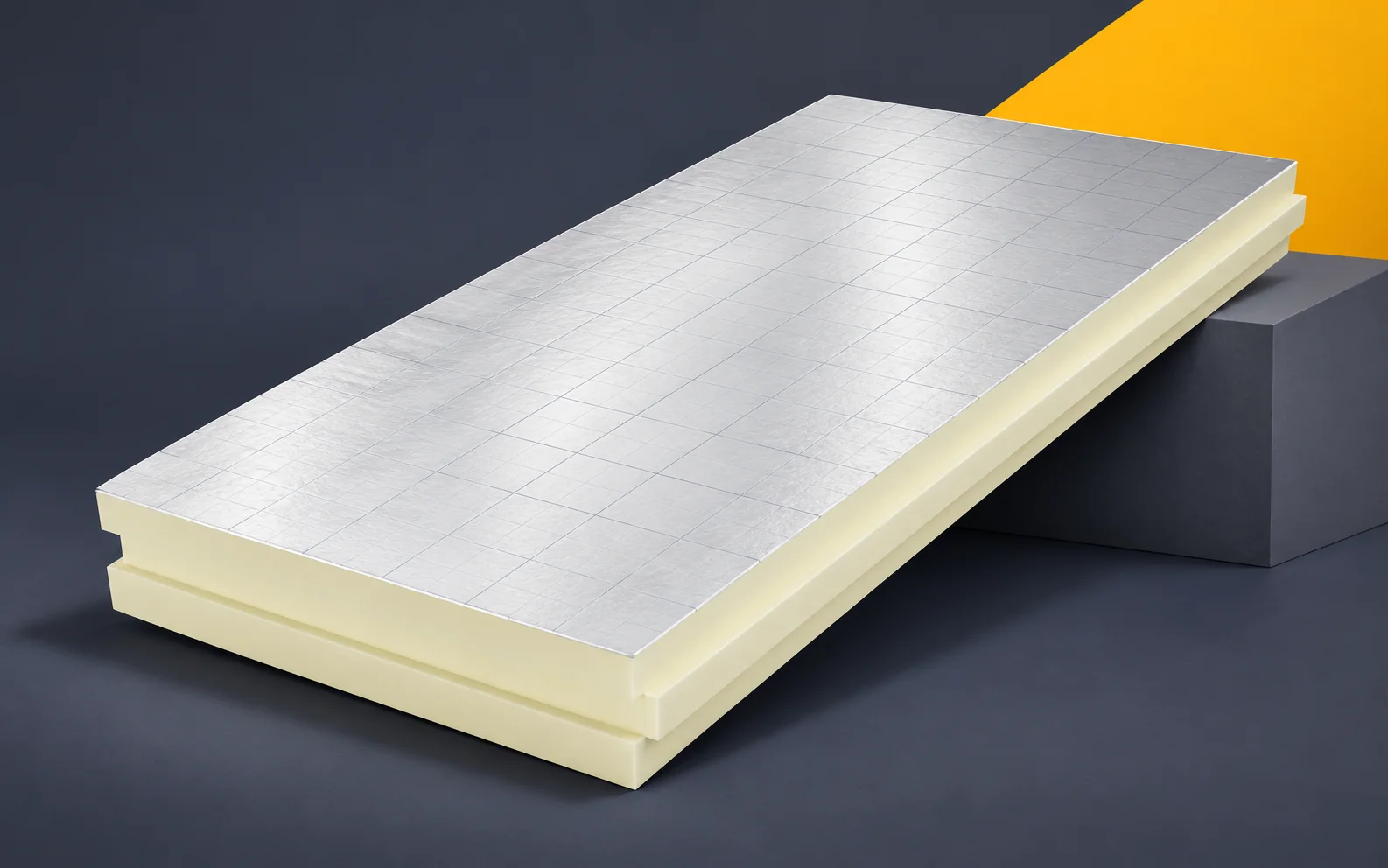
The scale of the detail is shown by an example: a window with assumed dimensions of 1.3 × 1.6 m has a perimeter of 5.8 m, and with 9 such openings this gives 52.2 m of junctions at reveals, lintels and zones below window sills. This figure is not a measure of heat losses nor a ready bill of quantities for accessories, but it shows how a small detail repeats across the façade. The wall design should therefore decide the solution for the openings, and the costing should distinguish their details from the regular field of thermal insulation. PIR boards for walls have different surfaces and purposes, and the insulation must match whether render, a cavity or internal cladding is created above it. The term polyurethane foam alone does not determine the interaction of the layers, so the full information on the wall build-up should be retained in the description.
7 branches. Materials closer to your project.