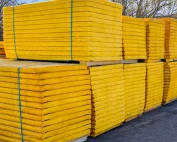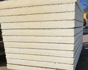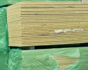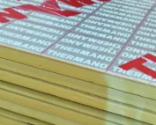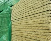
IDELCO α-therm WALL in building design: core, facings and joints
PIR insulation
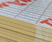
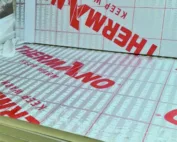
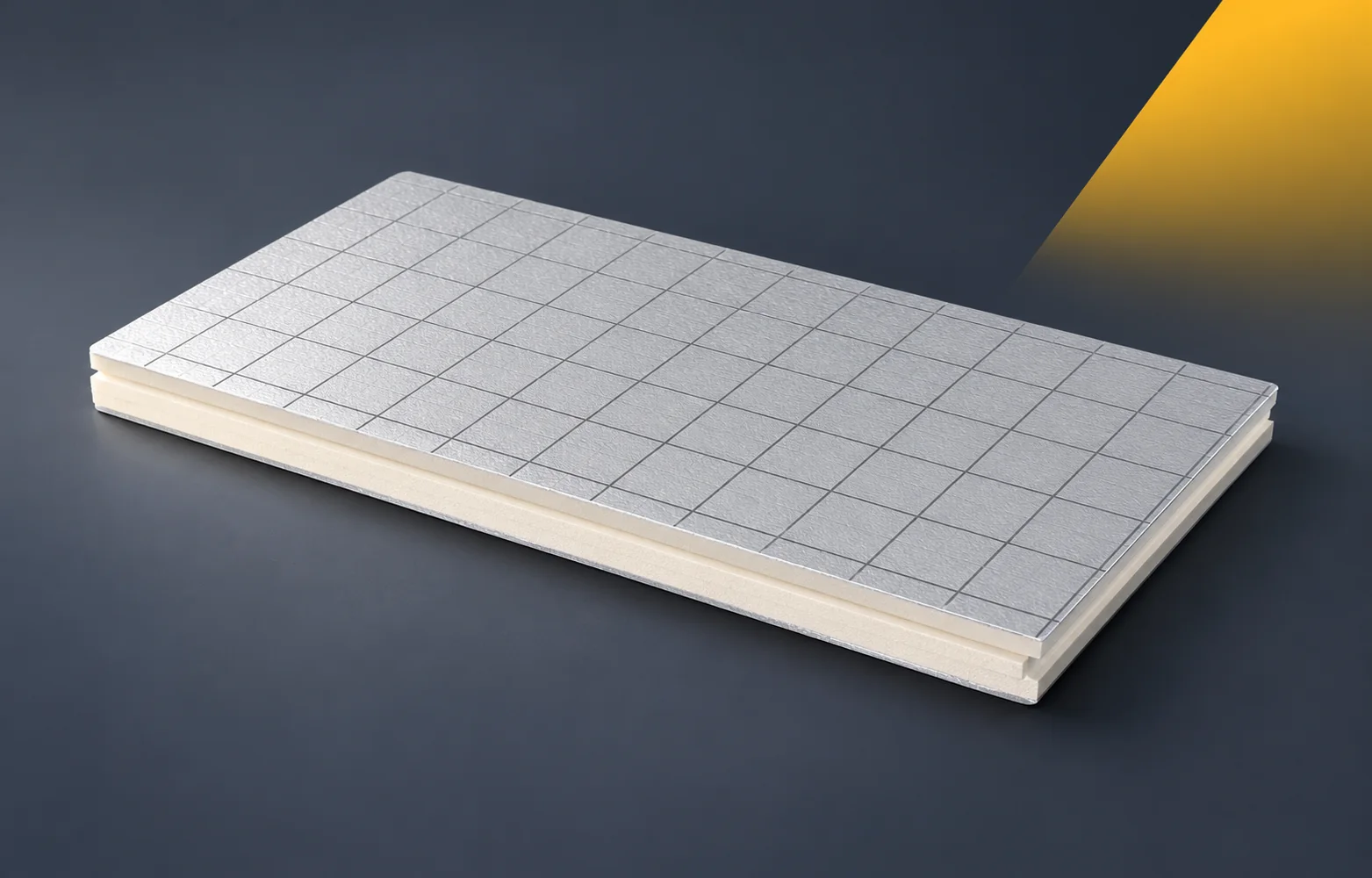
IDELCO α-therm WALL is a PIR board for insulation between the layers of a cavity wall, with both surfaces faced with aluminium laminate. The project must retain the data for this wall variant, because the parameters of a similar roof board do not provide a basis for assessing it. The specification should state the edge profile and the position within the building element so that the order is unambiguous. The description of use must clearly identify the α-therm WALL layer in the cavity wall and distinguish the insulation from the functions of the load-bearing wall and the anchors. The PIR designation is more precise than the broader terms “polyurethane boards” and “polyurethane foam”.
In this article
α-therm WALL PIR boards between the wall layers
The product name alone does not describe the solution: a PIR board with a laminate facing does not automatically take on the structural tasks of the wall. The aim is to use the low insulation thickness within a correctly planned cross-section. In the documentation, include the arrangement of the masonry, insulation and facing layer at the actual openings and indicate where it is to be used.
Lambda and the geometry of the building envelope
In the material table for α-therm WALL, thickness should be listed together with thermal resistance, not thermal conductivity alone. A 100 mm board corresponds to a declared R_D of 4.50 m²K/W; the lambda of this product is 0.022 W/(m·K). Other thicknesses available in the datasheet require reading off the thermal resistance specific to them.
Selecting wall insulation does not end at the area between its joints. In a design with α-therm WALL, the anchors and the geometry of the lintel and corner must be taken into account, which the thermal resistance of a single board does not describe. The documentation should include the wall cross-section and drawings of the insulation terminations; only on this basis can the selected thickness be related to the thermal requirement.
Polyurethane insulation with tongue and groove
The tongue-and-groove joint of α-therm WALL must be connected in such a way that the profile is not damaged and no open joints are left. When cutting the edge element, we change the factory finish, which is why this detail requires a conscious decision already at the drawing stage. The detailed design shows the tongue-and-groove joint at the last row and at the reveal.
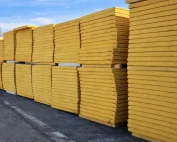
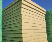
Plan the laying direction of the α-therm WALL 1200 × 600 mm boards on the construction drawing before the crew takes over the work: once the edges are cut, the piece loses the full geometry of the factory joint. The adopted laying plan allows the offcuts to be selected so that the tongue is not broken and no accidental gaps are left. For works inspection, indicate the laying plan, the condition of the profile and the termination at the perimeter, and establish an inspection before covering.
Water at the reveal and under the window sill
The protective layer of the wall and the insulation perform separate functions, so the design must provide for water drainage, the detailing of openings and the protection of the lower part of the wall. Analysis of the wall assembly includes drainage within the outer leaf that protects α-therm WALL.
Select the protections so that the function of the gap and the correct termination of the insulation under the window sill are preserved. The aluminium laminate of the insulation does not replace waterproofing or all masonry flashings, which must follow from the model and the detail. The material set combines protection against water with continuity of the thermal insulation, and the specification describes the drainage path, the terminations at openings and the possibility of the layers drying out without mixing the functions of the protective layers.
The correct data for the wall variant
The data sheet for this variant states a minimum of 120 kPa at 10% deformation and reaction to fire class F. The parameters of the ROOF roof board with a similar-looking surface cannot be attributed to it. The performance requirements for the wall are therefore described separately: CS of at least 120 kPa and reaction F.
The conformity assessment is carried out on the α-therm WALL documents, not on the data of a similar roof board. A shared brand and facing appearance do not mean identical mechanical properties. The design data should allow the wall requirements to be assessed on the basis of the correct product and configuration. When approving the product, check the full product designation and the documents relating to the intended use, as well as conformity with the design.
Insulation with polyurethane: quantity and acceptance before covering
Before purchase, determine the net wall area, the board format and how openings are to be detailed. The allowance results from the geometry, not from a fixed value repeated on every site. The purchase conditions also define the condition of the α-therm WALL edges before the protective layer is closed.
In the materials procedure, link the α-therm WALL quantity take-off with the openings and with protection of the material before the wall is closed. A damaged edge profile can make the joint difficult at a location that will later be inaccessible for inspection. The delivery agreement covers the quantity schedule, the cutting plan and the acceptance date for the insulation to be installed.
A case worth considering
The α-therm WALL specification must state the designation CS120. The CS value from the data sheet of the roof product relates to a different element and a different range of application, so it cannot be transferred to the wall. The requirements also cover the format, the edge and the fire conditions — only this set allows the supplied material to be assessed unambiguously.
7 branches. Materials closer to your project.