Refurbishing a building with cold-formed steel sections: checks before replacing the cladding
Profiles and steel structures
Replacing panels or installing new equipment may look like a minor intervention. For the structure, however, it means a change in loads, supports or connections. Cold-formed profiles in an existing hall must be assessed in their actual condition. The fact of many years of trouble-free operation alone does not confirm suitability for the new task. Modernisation should begin with identifying the layout before new cladding is ordered. Old drawings are an important source, but they do not always show all the changes made. They should be compared with the building. Cross-sections, lengths, spacings and connections are important. It is also necessary to establish whether there are additional openings, suspended elements or parts not visible in the original design.
In this article
Documentation should be checked against measurements
It is worth assigning the inspection findings to specific axes and elements. A general description such as ‘the purlins are in good condition’ may be too imprecise. It must be possible to trace back the location of the observation. This facilitates further calculations and the determination of the scope of any works.
The profile name does not reproduce its parameters
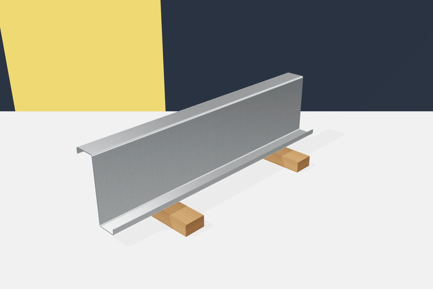
Z-sections, C-sections and sigma sections come in many geometries. Omegas also do not have a single universal cross-section. Similarity to a current catalogue is not sufficient to assign properties. The dimensions, thickness and material must be identified to the extent required for the assessment.
If the documents are incomplete, the person responsible for the assessment should determine further measurements or tests. The steel grade should not be guessed from its appearance. Galvanised sections may retain a similar surface over the years despite different substrate parameters. Identification requires separate attention.
New cladding may interact differently with the supports
Not only the weight changes. The permissible spans of the panels, the widths of the supports and the method of fixing may also differ. The possible stabilising function of the cladding must also be checked. The assumptions for the previous covering need not correspond to the new solution.
It is worth aligning the panel layout with the existing support grid. If the joints of the new panels fall in different places, additions may be required. The cladding lengths should not be ordered before these details are settled. Correction after material delivery is often considerably more difficult.
Equipment introduces specific forces
A new installation on the roof or a suspension requires the mass, position and method of fixing to be specified. General information about a small device is not sufficient. A local load may act differently from a uniformly distributed load on the cladding. Its transmission path must be analysed.
This also applies to the photovoltaic installation. It is not only the additional weight that must be assessed, but the entire assumed system of actions and connections. The available channel flange is not automatically a suitable mounting point. The solution should follow from an assessment of the whole structure.

An opening can change the load path of several elements
Cutting out a section of wall or roof may disrupt the support of the cladding, the continuity of the purlin or the bracing. The function of all parts at the point of intervention must be established. New framing and connections may be required. Their selection should take account of the existing arrangement, not just the size of the opening.
A purlin must not be removed simply because it obstructs the planned skylight. Likewise, cutting out a lip or web is a structural change. Cold-formed profiles owe their properties to their geometry. Removing a small section may affect a part that is essential to the element’s performance.
The temporary construction stage must be designed
Removing the panels may deprive the profiles of part of their support. The structure then behaves differently from before the modernisation began and after it is completed. The correct sequence and temporary supports are required. The delivery plan should be subordinated to this sequence, not the other way round.
The locations for storing materials must also be specified. A pack of new cladding constitutes a concentrated load on a specific zone. A short storage period does not remove the need for verification. Work organisation is therefore part of the safe solution, not merely the crew’s work schedule.
A change map with axis numbers is helpful. It allows the existing element, the new framing and the location of the additional load to be distinguished. This means the contractor does not have to reconstruct the scope of work from several descriptions. Such a plan also makes it easier to check whether a part intended to be retained has accidentally been removed.
The result of the assessment should be feasible to execute
The modernisation documentation should identify the elements that are retained, replaced and added. The connections and surface protection requirements must be specified. If work is carried out on existing galvanising, the method of further treatment must be agreed. Not every cosmetic repair restores the required properties.
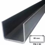
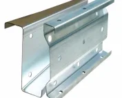
Channels, Z-sections, sigmas and omegas can facilitate reconstruction thanks to the possibility of preparing parts to size. Their use should, however, follow from the identified structure. A good modernisation design shows not only the target result but also the route to it without uncontrolled changes to the hall’s behaviour.
It is worth keeping the measurements and as-built documentation. Any subsequent extension will then be based on current data. This is particularly important when new parts are visually similar to the old ones but have a different material or hole pattern. Clear identification facilitates later assessment of the building.
7 branches. Materials closer to your project.